Measurements Tutorial
The Measurements tab is used to define the outputs and performance metrics that will be evaluated during simulation. Measurements can be configured for DC, AC, and Transient analyses, allowing users to extract circuit performance data for different simulation types.
The Measurements page also provides access to the Data Capture, Operating Points, and Component Nets sections, enabling users to capture simulation variables, define operating-point expressions, and reference circuit nets while creating measurements.
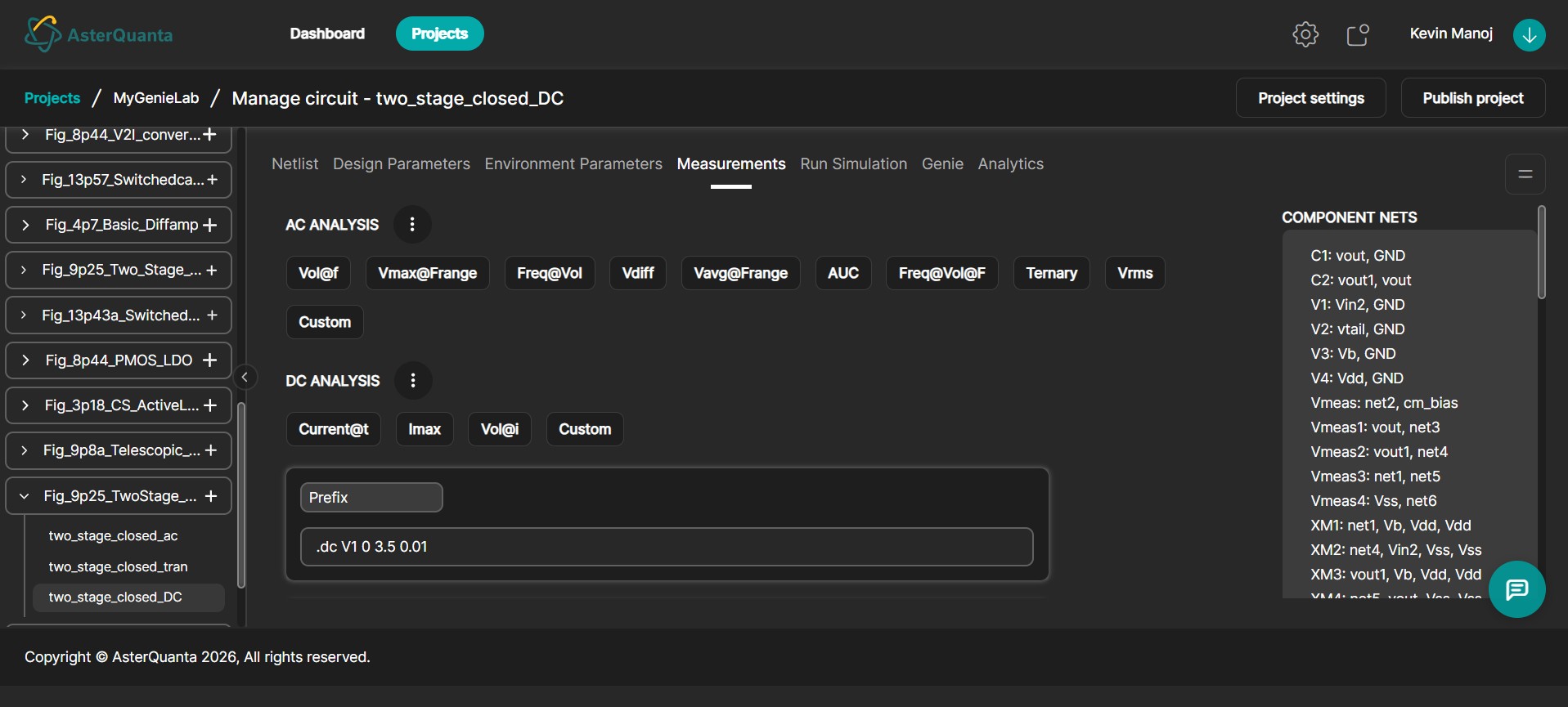
DC Analysis
The DC Analysis section is used to define measurements that will be evaluated during a DC sweep simulation.
The available measurement templates include:
Current@tImaxVol@iCustom
For this tutorial, a Custom measurement is used.
- Click Custom under the DC Analysis section.
- Enter a variable name for the measurement.
- Provide the measurement statement in the generated input field.
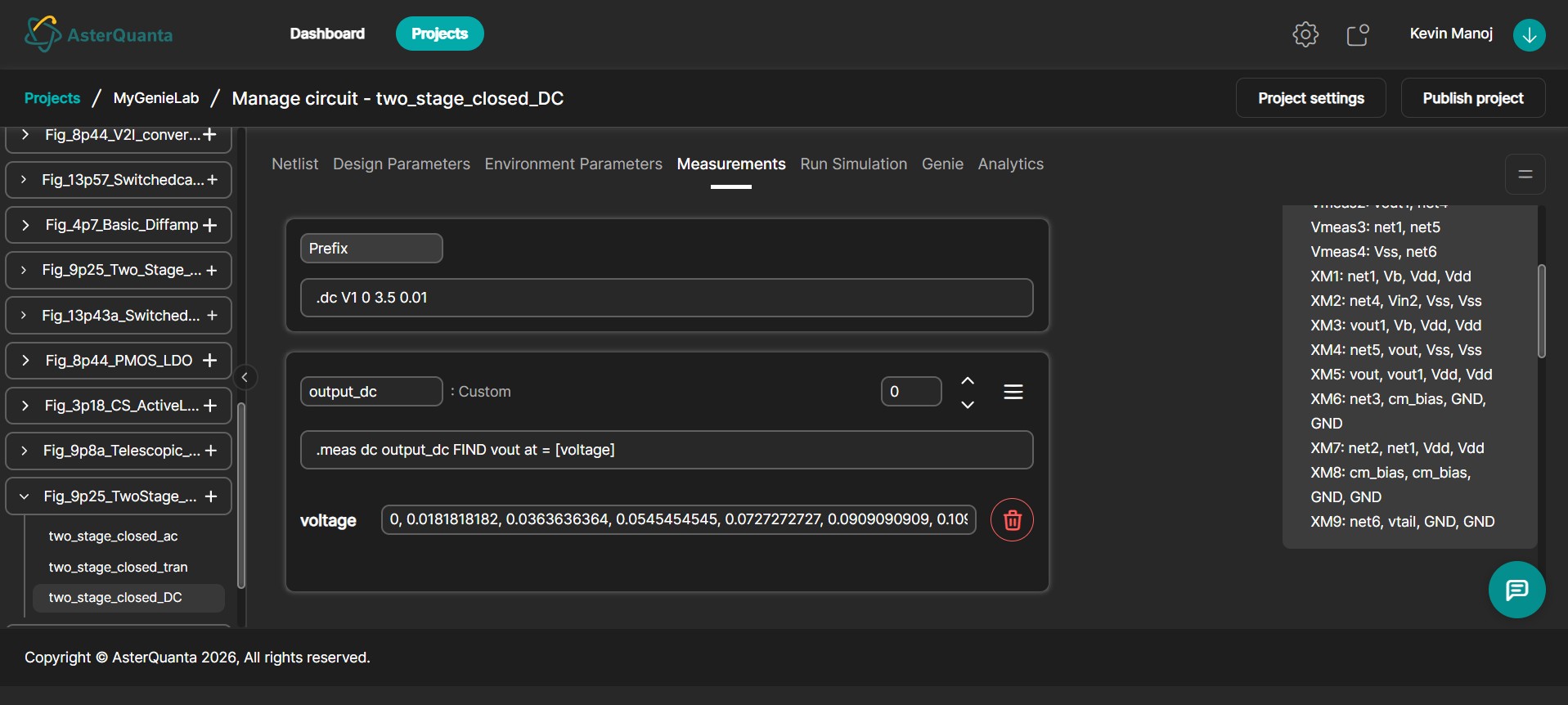
For this tutorial, a vector measurement is used to evaluate multiple voltage values on the vout net. A measurement label named output_dc is assigned to the measurement. The analysis performs a DC sweep using the voltage source V1.
To configure a vector measurement:
- Click the menu icon on the measurement card.
- Enable Vector Mode.
- Enter the variable name.
- Specify the measurement instances, separated by commas.
Measurement values may be entered manually or imported using a CSV file.
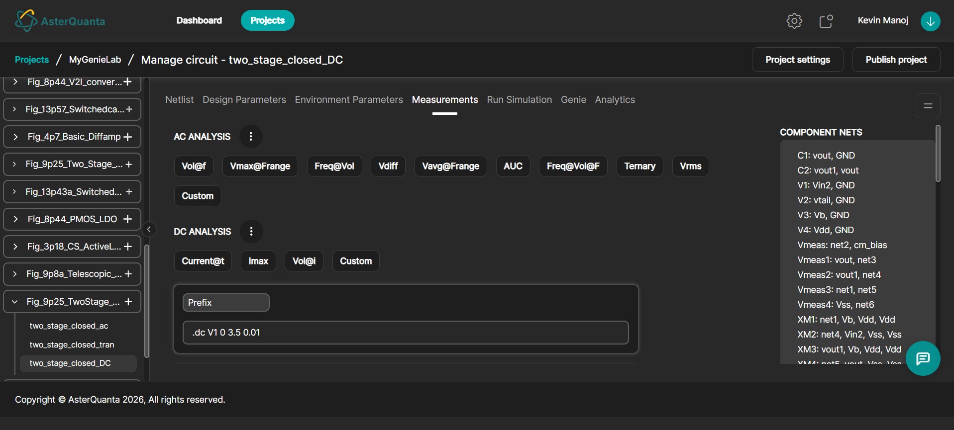
AC Analysis
The AC Analysis section is used to define measurements that will be evaluated during AC simulations.
The available measurement templates include:
Vol@fVmax@FrangeFreq@VolVdiffVavg@FrangeAUCFreq@Vol@FTernaryVrmsCustom
Select the required measurement template based on the analysis to be performed. If a predefined measurement does not meet the required evaluation, click Custom and enter the measurement statement manually.
For vector measurements, enable Vector Mode and specify the required frequency instances.
Measurement values may also be imported using a CSV file.
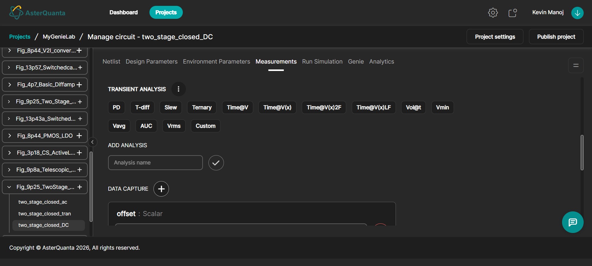
Transient Analysis
The Transient Analysis section is used to define measurements that will be evaluated during transient simulations.
The available measurement templates include:
PDT-diffSlewTernaryTime@VTime@V(x)Time@V(x)2FTime@V(x)LFVol@tVminVavgAUCVrmsCustom
Select the required measurement template, or click Custom to define a custom measurement statement.
For vector measurements:
- Enable Vector Mode.
- Specify the required time instances.
- Alternatively, import the measurement values using a CSV file.
Component Nets
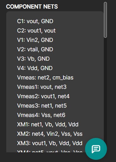
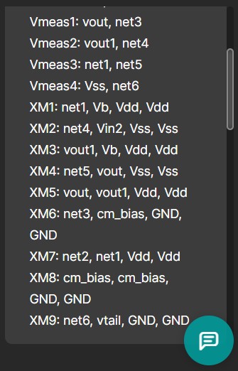
The Component Nets panel is located on the right side of the Measurements page. This panel displays all component connections and circuit nets extracted from the uploaded schematic or netlist.
Examples include:
voutVddGND
These nets can be referenced while creating measurements, eliminating the need to manually enter circuit node names.
Data Capture
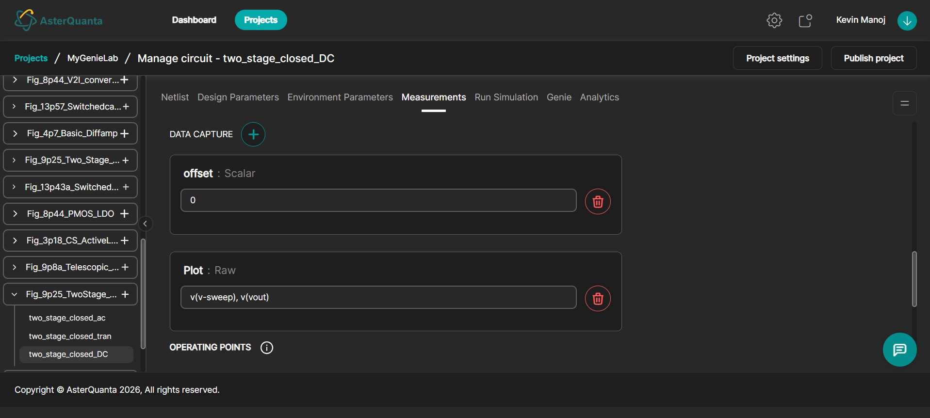
The Data Capture section allows users to capture variables that are defined directly within the netlist. This feature is commonly used with variables created using let statements, allowing the values to be referenced elsewhere in the project.
To add a Data Capture entry:
- Scroll to the Data Capture section.
- Click the Plus (+) icon.
- Select the required data type.
- Enter the variable name exactly as it appears in the netlist.
- Click Add Entry.
Data Capture supports both Scalar and Vector measurements.
| Measurement Type | Description |
|---|---|
| Scalar | Captures a single simulation value. |
| Vector | Captures multiple values across a simulation sweep or time interval. |
When creating a vector measurement, select Raw as the data type. Enter the measured nets and vector labels. For example:
v(v-sweep)
v(vout)
The first term identifies the sweep variable, while the remaining terms represent the measured outputs.
Vector data captured in this section can later be plotted from the Run Simulation tab.
Operating Points
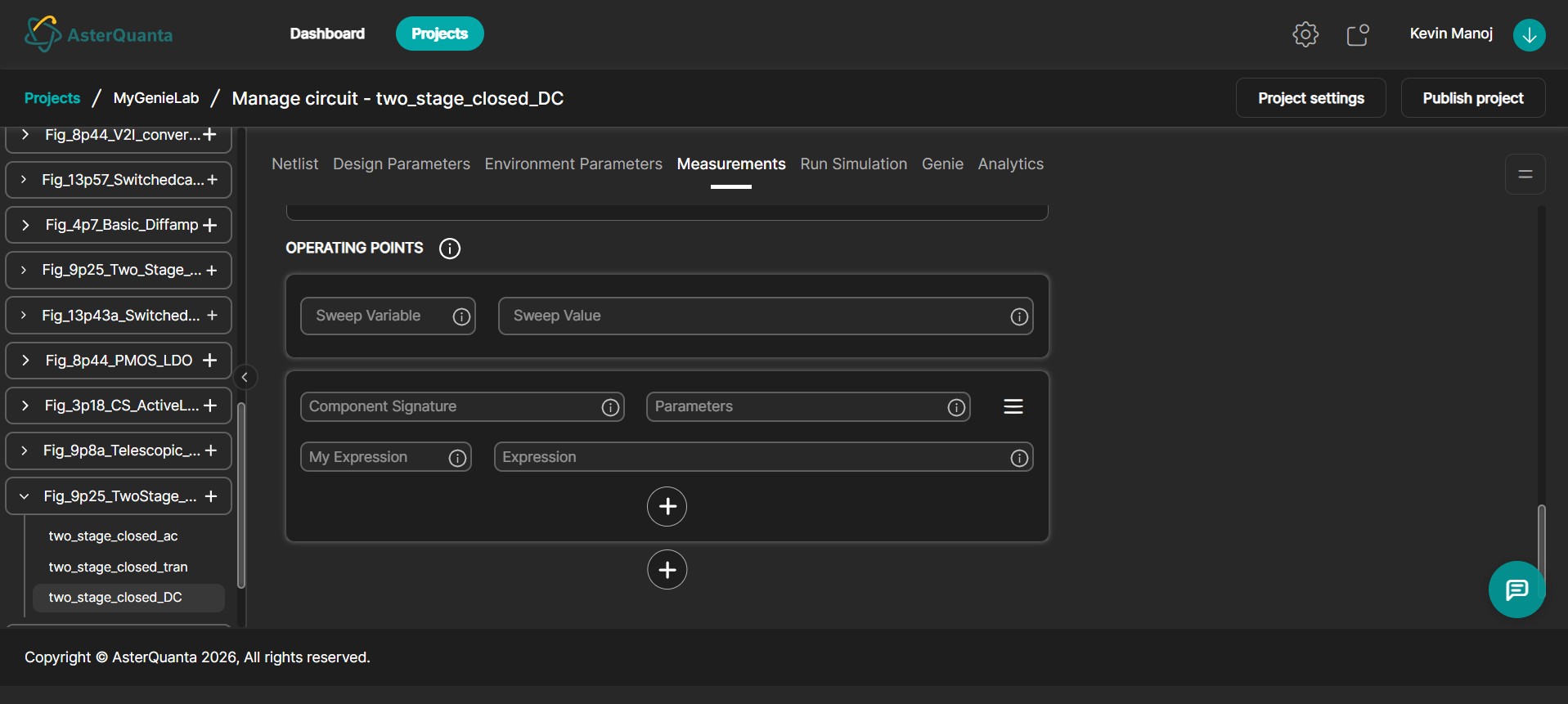
The Operating Points section is used to define operating-point based evaluations.
Users can configure:
- Sweep Variable
- Sweep Value
- Component Signature
- Parameters
- Expression Name
- Expression
Click the Plus (+) icon to create a new operating-point expression. Provide an expression name and define the required expression using the available circuit parameters. Multiple operating-point expressions can be added as required.
Notes
- Measurements are configured independently for each analysis type.
- Both scalar and vector measurements are supported.
- Vector measurements can be used to capture multiple values across a simulation sweep or time interval.
- Variables defined using Data Capture can be referenced by other features within the application.
- The Component Nets panel provides a convenient reference for available circuit nodes while creating measurements.